

Editor Settings

A user’s settings persist and do not reset at the end of a session.
- Data details: Details relating to the file currently open in the Label Editor.
- General: General interactions with the Label Editor.
- Label display: Toggle elements to show or hide those elements within the Label Editor.
- Drawing: Control how labels are drawn.
Data Details
The Data details section displays information about the asset currently open for annotation, or review. This information is gotten from the data itself, and is not available for direct manipulation. We use this section to provide you with valuable information about the data you are working on, including if we may have detected any possible issues with the data encoding.General Settings
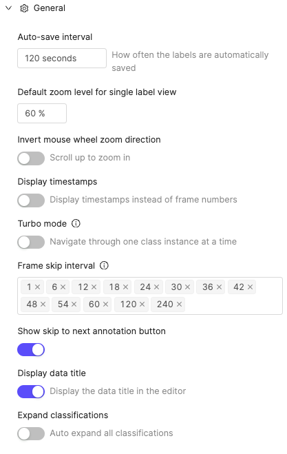 The General section of the Label editor settings contains the following components:
Label Display Settings

Medical Imaging Settings
This section of the Editor settings is only visible for medical imaging (DICOM) Projects.
Timeline Settings
The Timeline settings menu in Label Editors controls which labels appear on the timeline and how dynamic attributes behave. Access it from the Timeline panel in the Label Editor.Dynamic Attributes
Propagate across gaps is designed for objects that appear on disjointed frame ranges (sparse objects). When you enable this setting and set a dynamic attribute value, the value covers every later occurrence of the object automatically, stopping only at the next frame where you have explicitly set a different value for that attribute.
Drawing Settings
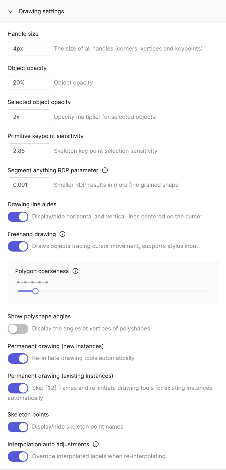
Object Tracking
Number of frames to predict Specify how many subsequent frames that SAM 2 should continue from the current frame. For example, if you start on frame 50, and set Number of frames to predict to 50, the tracker attempts to predict labels on frames up to and including frame 100. Advanced tracking This toggle enables the advanced SAM 2 tracking algorithm, which improves accuracy but runs at a slower speed. It is enabled by default.Scene
This section of the Editor settings is specific to PCD Projects and does not appear for other modalities.
Scene settings now persist across sessions. Your preferences for point cloud size, opacity, and helper visibility are automatically saved and restored when you reload the annotation editor.
General settings
General settings
Input DeviceSpecify using a
mouse or trackpad to rotate or pan in the workspace.Pre-load dataPre-load data in the background for smoother navigation. Enabling this setting can improve performance when annotating or reviewing point cloud data.Cuboid settings
Cuboid settings
FaceShows/Hides the “face” of cuboids in the PCD workspace.Show cuboid orientationControls how cuboid orientation appears in the PCD workspace. Select Front only to show an arrow that indicates the cuboid’s facing direction, All axes to show its three orientation axes, or None to hide orientation indicators. These indicators also appear on ghost cuboids while you preview their placement.Set front face from motionWhen enabled, Encord automatically orients the front face of a cuboid annotation based on the object’s local direction of motion whenever you add or paste a keyframe. It ignores small movements caused by annotation jitter. Encord re-orients existing keyframes for that cuboid in the same operation, except for frames where you manually set the front face during the current editor session, so undoing the action also reverts the orientation change.Setting the front face manually with Alt+ClickHold Wireframe cuboids in camera viewsEnable this setting to display unselected cuboids as outlines in camera-image views. Encord hides edges blocked by the cuboid itself or by other visible cuboids, making overlapping and stacked cuboids easier to inspect. The outlines use the configured label edge opacity. This setting is disabled by default and is available only for Scenes with camera channels.
This setting is disabled by default. When disabled, the front face follows how the cuboid was originally created. You can always set the front face manually at any time using
Alt+Click.Alt and click any face of a cuboid to designate that face as the front face on the clicked frame. The frame becomes a keyframe, and automatic orientation from motion does not override your selection during the current editor session. After you reopen the editor, a later automatic trajectory update may change that frame. Hold Alt+Shift and click a face to set the front face across every frame instead. These shortcuts work whether the cuboid is selected or unselected.While you hold Alt, Encord hides the cuboid’s drag-handle controls and makes the cuboid body the click target, so you can accurately pick the intended face without accidentally resizing the cuboid.When you set the front face across every frame, keyframes update their stored rotation, and interpolated frames rotate to match but retain their interpolated status.Show Cuboid TrajectoriesEncord always renders the full trajectory path for selected cuboids across frames. Enable Show Cuboid Trajectories to also display the trajectories of other eligible cuboids. Trajectory paths appear in the main 3D view, while the selected cuboid’s path also appears in the top-down (bird’s-eye) tile of grid view. The trajectory does not appear in front, back, left, right, or camera-view tiles — only the top-down tile shows it, because the path collapses to a point or line from those angles.Cuboids with only a single frame of annotation have no trajectory data and display nothing.
Helpers
Helpers
GroundShows/Hides the “ground” plane as a grid in the PCD workspace.AxisShows/Hides the axis of the point of origin in the PCD workspace.CamerasShows/Hides camera helper lines to aid in annotating PCD.Frames of referenceShows/Hides frame origins and the parent-to-child connections between them in the main 3D view. Arrows point from each parent frame to its child. Hover over a frame origin to view the frame name, parent frame, position, and quaternion rotation relative to its parent.BackgroundShows/Hides the background in the PCD workspace.
Color filter
Color filter
Click Filters in the 3D Label Editor Toolbar, then expand Color. The section reports when the loaded point cloud has no color or intensity data.Filter modesSelect a mode using the mode selector at the top of the section:
The color filter applies globally to all loaded point clouds in the scene. When you enable the filter, points outside the selected range are hidden in the viewport and cannot be selected by any segmentation tool.
- RGB — Filter points by red, green, and blue channel ranges (0–255 per channel). Available with Provided, Image color, and Sensor point cloud color modes.
- HSV — Filter points by hue, saturation, and value ranges. Available with Provided, Image color, and Sensor point cloud color modes.
- Intensity — Filter points by intensity range (0–100%). Available when the point cloud contains intensity data.
If the cuboid tool cannot resolve a point cloud in the rendered scene, it falls back to unfiltered selection for that cloud.
Mesh asset settings
Mesh asset settings
When a Scene contains mesh assets, use the Scene settings to inspect their geometry and appearance:
- Set Mesh appearance to Textured to display the asset’s colors, or Untextured to apply a neutral fill that makes its shape easier to inspect.
- With Untextured selected, enable Faceted shading to shade each triangle separately instead of smoothing the surface.
- Adjust Key light to control directional shading and Ambient light to control the even fill light. These lighting preferences persist across sessions.
These settings appear only when the Scene contains a mesh asset. They do not affect point-cloud-only Scenes.
Point cloud settings
Point cloud settings
A Scene can optionally include view settings which will be applied when opening it, such as the point cloud size and coloring mode. See Scene view settings to learn more.
- Solid: Displays points with a single uniform color.
- Height: Displays points in colors based on the distance from the “ground” plane. Selecting this mode shows Height color range in the Scene settings, where you can adjust the displayed range.
You can adjust the “ground” plane using the ground height feature on the Editor toolbar.
- Provided: Displays points in colors based on how they were originally captured and recorded. Available when a point cloud includes color data.
- Image: Displays points in colors by projecting camera image data onto the points. Available when the scene includes cameras.
- Sensor: Displays points colored by the sensor that captured them, making it easy to visually identify which sensor contributed which points in a multi-sensor setup. Available when the scene includes multiple point cloud streams.
- When you enable Color by sensor mode, points from different sensors are automatically assigned distinct colors from a fixed palette of 20 maximally distinct colors.
- Sensor colors are assigned consistently based on the sensor’s stream ID, so the same sensor is always use the same color across different frames and sessions.
- Show: Displays point cloud data in the PCD workspace.
- Merge: Displays all point cloud data across time in the PCD workspace.
-
Hide segmented: Hides all point cloud data that is behind segmented objects in the PCD workspace.
Only segmented objects that are set to be hidden hide all point cloud data behind them.
-
Hide Unsegmented: Hides all points not covered by any segmentation label. This toggle is off by default. You can also toggle this setting using
Shift+U.When you enable Hide Unsegmented before creating any segmentations, no points are hidden because no segmentation coverage exists yet.You can combine Hide Unsegmented with Hide segmented to show only points that belong to visible segmentation labels.
Point cloud size
Point cloud size
Specify the size of cloud data points in the PCD workspace.
Point cloud opacity in 2D views
Point cloud opacity in 2D views
Specifies the opacity of PCD in 2D views.
The default value is 0. PCD does not display in 2D views with a value of 0.
Render full camera image
Render full camera image
Renders the full image captured by the camera beyond the source image’s nominal bounds. Enable this setting when working with wide-angle or fisheye lenses in 3D scenes to display the complete captured area in the rectified camera view.
This setting is off by default. When disabled, the rectified camera view clips to the source image’s nominal bounds. This setting is only visible when you are working in a 3D scene context.
Ground mesh fitting
Ground mesh fitting
The ground mesh fitting tool improves ground detection in LiDAR/point cloud scenes, including curved roads and uneven terrain. Encord automatically detects and fits the mesh in the background as the scene loads. You can then activate it as an overlay in the 3D viewer, giving you a visual reference for scene geometry and making it easier to focus on objects of interest.Ground segmentationEncord automatically segments the point cloud into ground and non-ground points as the scene loads. Click Adjust ground in the toolbar, then Use ground mesh when the detected mesh is ready. To switch back without discarding the detected mesh, click Use ground plane. The segmentation algorithm handles curved and uneven terrain more accurately than a flat ground plane.Height filter integrationWhen you fit a ground mesh, the Height section of the Filters panel gains a Ground mesh mode. In this mode, the height filter measures each point’s height above the local mesh surface rather than a flat plane, enabling accurate filtering over curved or uneven terrain such as cambered roads or hilly ground.To use the height filter with a fitted ground mesh:Click Remove ground to set the minimum height from the fitted mesh’s detected ground level and hide points identified as ground.Lasso (freehand) and brush segmentation tools respect the ground-mesh-relative height filter when Ground mesh mode is active, so only points above the mesh surface at the specified height range are included in your selection.To open or close the Filters panel, press
- Click Adjust ground in the toolbar, then click Use ground mesh when the detected mesh is ready.
- Close the Adjust ground pane.
- Click Filters in the toolbar, then expand Height.
- Select Ground mesh from the mode selector. The selector shows Ground mesh when a fitted mesh is active, or Ground plane when only a flat ground plane is available.
- Adjust the Min and Max bounds. The histogram and range reflect heights above the mesh surface.
The Ground mesh option appears in the height filter mode selector only when a fitted ground mesh is active. If no ground mesh has been fitted, the selector shows Ground plane instead.
F. Use the reset button beside Height to clear the height filter.When you select a cuboid and click Level, Encord aligns the cuboid with the local slope of the active ground mesh. If you use the ground plane instead, Level aligns the cuboid with that plane. The action preserves the cuboid’s position, size, and heading.Cuboid fitting on the ground plane currently uses the flat ground plane, not the terrain mesh. Full integration with the terrain mesh is planned for a future release.
Ground mesh fitting runs in the browser. On large or merged point clouds, the fitting process may temporarily affect UI responsiveness while it completes.
Faded point opacity
Faded point opacity
Specifies the opacity of data points that fade into the background. For example, all data points outside of a Scene slice.
Color points inside cuboids
Color points inside cuboids
Controls whether points that fall inside cuboids are highlighted with special coloring to make them more visible. This setting overrides the normal point coloring mode for points contained within cuboid annotations.
Label color mode (review)
Label color mode (review)
Controls how 3D labels are colored during workflow review and consensus review tasks. This setting applies to all 3D label types: cuboids, spheres, polylines, and keypoints/points.By review statusWhen you set Label color mode (review) to By review status, all 3D labels in the point cloud viewport are recolored according to their current review state:Selected 3D labels retain their review-status fill color when selected. Only the selection outline switches to the selection highlight color, matching the behavior in 2D review tasks.
This setting only takes effect when you are in a workflow review stage or consensus review stage. It has no effect outside of review tasks.
Labels you action (approve or reject) during the current review session fade to the opacity configured in Reviewed label opacity, reducing visual clutter as you work through the scene.
The opacity fade applies only to filled shapes — cuboids and spheres. Polylines and keypoints/points are recolored by review status but do not fade.
Reviewed label opacity
Reviewed label opacity
Specifies the opacity applied to 3D labels that you have actioned (approved or rejected) during the current review session. Reducing this value fades reviewed labels into the background, making it easier to focus on labels that still require review.
The opacity fade applies only to filled shapes — cuboids and spheres. Polylines and keypoints/points are recolored by review status but are not affected by this opacity setting.
This setting only takes effect when Label color mode (review) is set to By review status and you are in a workflow review stage or consensus review stage.
In-editor tutorials (Scene projects)
In-editor tutorials (Scene projects)
Scene-type (3D LiDAR/point-cloud) projects include interactive in-editor tutorials you can access directly from the label editor. Each tutorial guides you through a specific workflow step by step, and the editor automatically detects when you complete each action so the tutorial advances in real time.Accessing tutorialsClick the Help button in the top toolbar, then select Tutorials. The tutorials panel lists all available tutorials for your project type. Click Start on any tutorial card to begin.Cuboids across timeThe Cuboids across time tutorial teaches you the full multi-frame cuboid tracking workflow. It takes approximately 5 minutes and covers the following steps:
- Select a cuboid — select an existing cuboid in the 3D view.
- Copy the cuboid — copy the selected cuboid to the clipboard.
- Place it on a later frame — navigate forward several frames, then hold
Shiftto preview the copied cuboid and click to place it. - Interpolate between keyframes — fill every frame between your two keyframes using the interpolate shortcut or the right-click menu.
- View the trajectory — review the trajectory the editor draws between keyframes, then confirm with OK.
- Turn on auto re-interpolation — enable Auto interpolate under Drawing in the editor settings so the editor automatically re-runs interpolation when you adjust a keyframe.
- Edit the trajectory in grid view — open grid view, drag the cuboid in any frame column to refine its position, and close grid view when done.
- Set the front face — use
Alt+click to set the front face on the current frame, or addShiftto set it on every frame. - Toggle a keyframe — use
Alt+Kto unmark or re-mark the current frame as a keyframe. - Lock the size — click Lock size in the cuboid pane to enforce a uniform size across all frames.
- Make it static — use
Alt+Sor the pushpin in the cuboid pane to mark the object as static, copying its current pose to every frame.
The Cuboids across time tutorial is only available in Scene-type (3D LiDAR/point-cloud) projects. It does not appear for other project types.
Metadata Panel
The metadata panel displays item metadata for the currently open data unit in the Label Editor. Access the metadata panel using the Metadata button (code icon) in the editor header. This feature can be enabled or disabled per account. Admins may wish to disable it if task metadata contains sensitive information that should not be visible to Taskers.
The metadata panel only appears when metadata is available for the current data unit
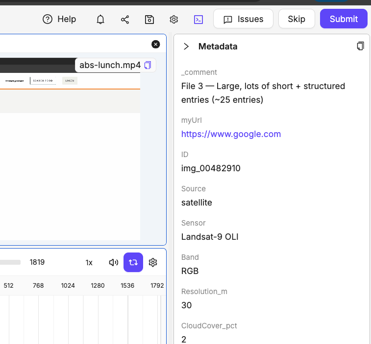
- Field-by-field display: Each metadata field appears with its key and value clearly separated
- Copy functionality: Click any field to copy its value to your clipboard, or use the copy button in the header to copy all metadata as JSON
- URL detection: URLs in metadata values automatically become clickable links
- JSON formatting: Complex nested objects display as formatted JSON for better readability
- Large metadata handling: Very large metadata files show a message directing you to use the copy function
- Embedding field filtering: Fields containing “embedding” in their names are automatically hidden from display to improve readability. Hidden fields are listed in a “Hidden fields” section at the bottom of the panel.
Embedding-related metadata fields are automatically filtered out of the display but remain accessible through the copy function. The panel shows which fields were hidden in a “Hidden fields” section.
Trackpad Support
Encord’s Label Editor supports trackpad gestures for improved navigation and annotation workflows. This feature works alongside traditional mouse controls to provide a more intuitive experience when using laptops or external trackpads.Trackpad Gestures
The Label Editor recognizes the following trackpad gestures:- Pinch-to-zoom: Use two fingers to pinch in or out for precise zoom control. Pinch out (fingers apart) to zoom in, pinch in (fingers together) to zoom out.
- Two-finger scroll: Use two fingers to pan around the canvas. The content follows your finger movement naturally.
Trackpad support is automatically enabled when you set your input device to “trackpad” in the Scene settings. For non-scene projects, trackpad gestures work automatically when detected by your browser.
Input Device Configuration
For point cloud data (PCD) Projects, you can specify your preferred input device in the Scene settings:- Open the Editor settings panel
- Navigate to the Scene section
- Under General settings, select your Input Device:
- Mouse: Optimized for traditional mouse interactions
- Trackpad: Enables trackpad gesture recognition and optimized sensitivity
Gesture Behavior
Zoom behavior:- Trackpad pinch-zoom provides smooth, proportional zooming based on your gesture speed
- Zoom centers on your cursor position for precise control
- The Invert mouse wheel zoom direction setting also affects trackpad pinch direction
- Two-finger scroll moves the content in the direction of your fingers
- Panning disables auto-centering, preserving your chosen view across frame changes
- Pan sensitivity is optimized for trackpad input
When using trackpad mode, two-finger scroll is dedicated to panning. Frame navigation using scroll gestures is disabled to prevent conflicts with pan gestures.
Keyboard Shortcuts
The words ‘keyboard shortcuts’ and ‘hotkeys’ are used interchangeably and refer to the same concept.
Windows and Mac may have different keyboard shortcuts. Use Control + Shift + K to open the full list of shortcuts
Actions Menu
The Actions menu provides quick access to all available Label Editor functions through a searchable interface. Access it using Ctrl + K (Windows) or Cmd + K (Mac). The Actions menu includes:- All keyboard shortcuts with their hotkey combinations
- Editor settings and configuration options
- Navigation and tool selection commands
- Automated labeling functions
- All Ontology classes for annotation creation, including those without assigned hotkeys
In large Ontologies where not all classes have assigned hotkeys, the Actions menu displays all available annotation classes, making it easy to create labels for any object type in your Ontology.
Some actions — such as Go to middle frame — have no default keyboard shortcut assigned. These actions still appear in the Actions menu and are fully functional. You can assign a custom shortcut to any unassigned action via the hotkey customization settings. Contact support@encord.com to enable hotkey customization for your account.
Review Mode
Single label review:
Single label review can be enabled using the hotkey CTRL+SHIFT+T
General
Select a timeline row before using the range-edge shortcuts to keep navigation within that row. Navigation stops at the row boundary and displays There are no annotated frames in that direction. If no row is selected, the shortcuts navigate range edges across all rows. For a collapsed classification or object group, the shortcuts navigate ranges for every instance in the group. For an individual instance row, they navigate only that instance’s ranges.
The hide or show shortcut applies only to selected labels. For a mixed selection of visible and hidden labels, it hides every selected label; if every selected label is hidden, it shows them all. The shortcut has no effect when no labels are selected. When the right-click menu containing Hide is open, the shortcut only hides the selection and does not show an already-hidden selection.
On Mac, use Control + Option + the arrow key. On Linux systems that reserve these combinations for switching workspaces, change the conflicting system shortcut. If hotkey customization is enabled for your account, you can customize the Label Editor shortcut instead.
Keyframes:
These keyframe shortcuts belong to the legacy dynamic-attribute keyframe workflow and are not available in the current timeline. Dynamic attributes are now edited as frame ranges (blocks). See Dynamic attributes for the current workflow.
Annotate Mode
Common Actions:Go to middle frame has no default keyboard shortcut. You can assign one via the hotkey customization settings in the label editor.
Draw Polygon Mode:
Draw Bitmask Mode:
DICOM specific operations:
Bulk 3D Scene Editor Copy/Paste keyboard shortcuts
Label Editor Settings Templates
Workspace and Project Admins can configure Label Editor templates to provide a consistent and optimized experience for their annotators and reviewers on a Project. Annotators and reviewers can make the choice of using the Label Editor settings or customizing the Label Editor settings.Configure Label Editor Settings templates
Only Workspace and Project Admins can create Label Editor templates.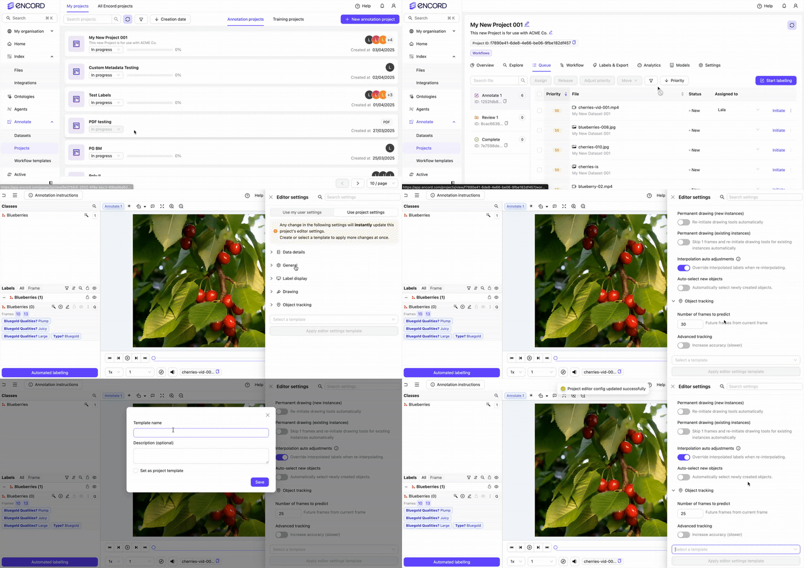 To create a Label Editor Settings Template:
- Go to Annotate > Projects > [select a Project]. The Project page appears.
- Click Queue. The Task Queue appears.
- Click Initiate for a data unit in the queue.
- Click the Editor settings icon. The Editor settings panel appears.
- Click Use Project settings. The Use Project settings panel appears.
- Specify the Label Editor settings you want your annotators and reviewers to use in the Project.
- Click Select a template.
- Click Save current settings as template. A dialog box appears.
- Provide a meaningful name and description for the template.
- Click Set as template to use the template in the current Project.
- Click Save.
Apply a Label Editor Settings Template
Only Workspace and Project Admins can apply Label Editor templates to Projects. Apply Label Editor Settings Template To apply a Label Editor Settings Template to a Project:- Go to Annotate > Projects > [select a Project]. The Project page appears.
- Click Queue. The Task Queue appears.
- Click Initiate for a data unit in the queue.
- Click the Editor settings icon. The Editor settings panel appears.
- Click Use Project settings. The Use Project settings panel appears.
- Click Select a template.
- Select the template you want to use.
Use Your Own Label Editor Settings
Annotators and reviewers can use their own settings instead of the Label Editor Setting template settings.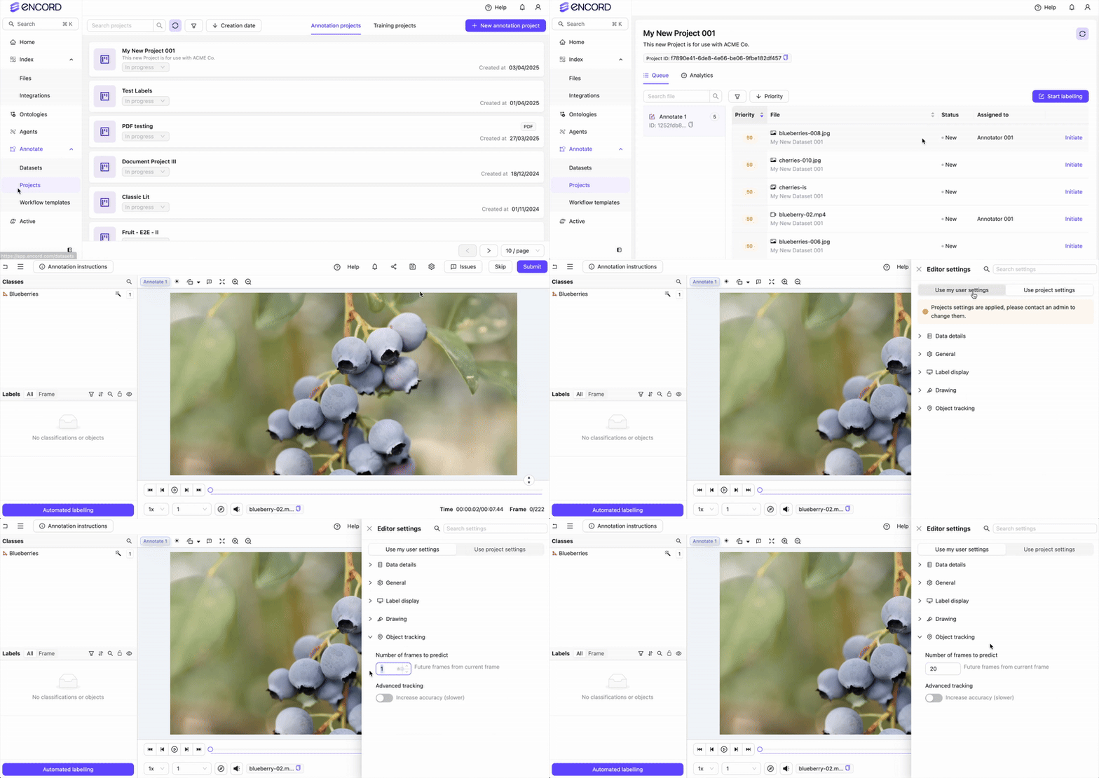 To use your own settings instead of the Label Editor Template settings:
- Go to Annotate > Projects > [select a Project]. The Project page appears.
- Click Queue. The Task Queue appears.
- Click Initiate for a data unit in the queue.
- Click the Editor settings icon. The Editor settings panel appears.
- Click Use my user settings.